

- Common shaft lengths: 16, 20, 23 mm. Calipers measure to 0.001 in (~0.02 mm).
Quick picks
Essential tools & parts

Measurements
Pre‑purchase measurement checklist
- Overall dial diameter
Measure the visible face across the widest point, not including bezel or mounting flange. Note both outer diameter and the usable aperture if the dial sits behind a bezel.
Record these preciselyOuter diameter and usable aperture in millimetres (or inches).Common mistakes to avoidRelying on case size or approximate numbers from pictures. - Center hole and shaft specifications
Record the center hole diameter and whether the movement uses a round shaft, tapered shaft, or a threaded onion-style post. Measure shaft length from the movement plate to the outer face and shaft diameter at the hand-bushing area.
Record these preciselyExact shaft type, shaft diameter, and exposed length (metric).Common mistakes to avoidAssuming standard shaft lengths or only noting total movement size. - Mounting holes: pattern and offsets
Measure the number of mounting holes, their diameters, and the center-to-center distances or bolt circle diameter. Also note the offset from the dial center to any screws or locating pins.
Record these preciselyHole count, bolt circle diameter (BCD), and radial offset from center.Common mistakes to avoidCounting holes visually without measuring spacing or offset. - Movement thickness and hand clearance
Measure movement depth and the clearance between the dial face and minute/second hands. Note minute hand length from center to tip so hands won’t overhang or rub the bezel.
Record these preciselyMovement depth and hand length/clearance values in mm.Common mistakes to avoidIgnoring hand profile or assuming thin movements fit all dials.
- Gather the right tools
Lay out a digital caliper (0–6 in is versatile), a rigid ruler or tape, small screwdrivers, soft gloves or finger cots, a lint‑free cloth, and a smartphone or camera. Include a small bit of masking tape and a pen for labelling parts.
- Power down and remove hands safely
Stop the movement and remove power or weights. Use gloves to gently lift hands straight off their posts—avoid twisting. If the hands resist or the movement is unfamiliar, remove the whole movement instead of forcing hardware.
- Stabilize the dial for repeatable measures
Place the dial flat on a clean, non‑slip surface or on a padded block to keep it level. For hole and thickness measures, support the dial near the measurement point so the caliper jaws sit squarely.
- Photograph every view with scale
Take clear photos of the front, back, and any mounting holes with a ruler or caliper in frame for scale. Capture close‑ups of the shaft opening, keyways, and surrounding markings—use even light and a macro mode if available.
- Name files and record measurements
Save photos with structured names (e.g., 2026-06-16_Seiko123_dialOD_135mm.jpg). Log measurements in one place with units and tolerances (e.g., hole C‑C: 23.0 mm ±0.2 mm). Repeat each critical measure twice and note which instrument was used.
Delicate parts: painted dials, thin hands, and pivots can bend or chip easily. Do not pry or force components; use minimal pressure when measuring. If corrosion or stubborn fittings appear, consult a clockmaker—photos and careful notes are safer than brute force.

Precision caliper, 0–6 in
Digital caliper accurate to 0.001 in with stainless‑steel construction and a large LCD for quick readouts. Features zeroing at any position, inch/mm conversion, and factory calibration. Good choice for measuring shaft diameters, hole centres, and dial thickness on clocks.
Dial & aperture measurement
How to measure overall diameter and the center aperture
- Measure overall diameter
Use digital calipers across the face at the widest point, reading in millimetres and inches. If a bezel or rim sits above the face, remove it or measure edge‑to‑edge on the same reference plane to capture true diameter.
- Handle non‑round dials
Measure both the major and minor axes by taking the longest and shortest cross‑sections at 90° and record orientation (for example, vertical major axis). For rectangular or square faces, also note corner‑to‑corner diagonals if they affect mounting.
- Measure the center aperture
Use the caliper’s inside jaws to measure the inner diameter of the center hole; for countersunk or tapered apertures measure top diameter, bottom diameter and depth. For slots or keyholes, record long and short dimensions and the slot centerline direction.
- Account for applied features and subdials
Avoid measuring across raised hands, numerals, or subdials unless those raised elements define required clearance—measure the substrate plane for nominal diameter. For movements with subsidiary arbors, record center‑to‑center distances between main and subdial centers.
- Verify and avoid common pitfalls
Watch jaw misalignment, parallax with rulers, and inconsistent units; photograph the caliper in place next to a scale and repeat measurements to confirm. Allow and note a small tolerance (commonly ±0.3–0.5 mm) when comparing parts.
Shaft geometry
How to measure shaft/post geometry step‑by‑step
- Prepare tools and notation
Use digital calipers (0.01 mm or 0.001 in), a ruler for scale, and a thread gauge or a microscope/photo for pitch. Record units (mm and inches) and the movement’s seating face as the zero reference.
- Measure total shaft length
Measure from the movement’s seating face (where the shaft exits the case) to the tip of the post; this is the total length. Photograph a side profile with calipers or a ruler clearly touching both reference points.
- Measure threaded portion, shaft diameter and pitch
Measure the threaded length from seating face to end of threads, and the shaft major diameter with calipers. Determine thread pitch with a gauge or by measuring the distance over 10 threads and dividing by 10; report as mm pitch or TPI. Include a close-up photo of the threads with a nut engaged to show fit.
- Calculate usable length through the dial/bezel
Measure bezel and dial thickness where the shaft passes; usable length = total length − (dial + bezel thickness) − allowance for washer/nut (typically 1–2 mm). Photograph the movement assembled through the dial showing remaining exposed shaft with a scale.
- File photos and hand a clear summary to suppliers
Provide labelled photos: front dial with center hole, side profile with scale, thread close-up with nut, assembled-through-dial. Name files like model_total-thread-dia.jpg and include both metric and inch values and a tolerance (±0.5 mm). Cross-check against measurements for shaft length.
Hand fittings Hour, minute and seconds — exact specs sellers need
Measuring pivot hole diameters
Understanding the pivot hole sizes is essential to confirm hand‑to‑movement compatibility. Record actual inside diameters, any tapers or steps, and which face of the hand sits toward the dial.
Measuring technique
- Use calipers’ inside jaws to read the hole diameter; take three readings at different rotations and average. Report to 0.01 mm (or state caliper resolution).
- For tapered holes, measure the top and bottom diameters and note which is toward the dial. For stepped holes, measure each step diameter and the step depth with a depth gauge or thin probe plus calipers.
- Measure the hand’s mounting-hole thickness (material thickness at the hub) and note the hand’s front/back orientation.
Photos and reporting
- Provide close-up photos with caliper jaws visible and the numeric reading, a side profile showing taper/step, and a full-hand shot next to a ruler to determine minute hand length.
- Report example (concise lines):
- Hour hole: 2.45 mm (front), Minute hole: 1.50 mm (back), Second: 0.60 mm; Taper top/bottom; Step depth 0.8 mm; Hand thickness 0.25 mm. Attach filenames of the three required photos.
Hand-fit types
Common hand-fit types and how they affect replacements
- Cannon pinion
A hollow, splined hub that slides over the minute shaft and transmits motion to the hands; replacements must match spline/profile and inner diameter, so full-hand swaps often require a matching cannon pinion or a hand with the correct hub.
- Press‑on / stepped
Hands with one or more inner diameter steps that press onto corresponding shaft shoulders; exact step diameters are critical — mismatches need stepped adapters or careful reaming to avoid looseness or damage.
- Tapered
Conical bores that rely on friction against a tapered shaft; interchangeability depends on taper angle and size; minor mismatches can be corrected with taper sleeves or by reshaping the shaft, after first [nodelink id="fe0302dc-1d1f-4fe5-8df1-c1c4d5b80e59"]identify mounting hole and hand fit.
- Hollow (post‑fit)
Large, through-bore hands that fit over posts or tubes (common for seconds/subdials); replacement selection centers on inner diameter, depth and whether washers or friction bushes are needed to achieve correct height and clearance.
Measurement myths
Common measurement mistakes — what they miss and how to fix them
Measure face-to-mounting-plane depth; note stepped depths.
Double-sunk faces create two planes that alter hand clearance; incorrect depth causes binding—use a depth mic or feeler gauges and photograph cross-sections.
Pocket diameter and depth set movement clearance.
Shallow pockets can push the movement outward or restrict hand sweep; measure pocket depth and consider shims or spacer rings as corrective options.
Shafts vary—splined, D-flat, stepped, or extra long; document profile and usable exposed length.
A mismatched profile prevents proper hand seating or strips hubs; supply macro photos, spline counts, and caliper readings so adapters or custom hubs can be specified.
Thick inner lips shorten the usable spindle and can block hands.
Measure bezel inner depth from the dial face—if insufficient, choose a longer spindle, a thinner bezel, or add a spacer ring to restore clearance.
Send these with inquiries:
Close-up of the shaft/profile with caliper reading and a ruler for scale. Depth shot showing double-sunk or recessed pocket with a depth mic or probe visible. Bezel inner-lip measurement and overall dial diameter (top and side views preferred).Verify with low‑tech checks
Simple templates and mock-ups before ordering
- Cardboard or foamboard template
Trace the dial outline and center hole onto stiff cardboard. Cut out and test fit against the case to confirm overall diameter, bezel clearance, and screw locations.
- Paper hand mock-ups
Print or draw hands at scale, punch center holes, and mount them on the actual shaft or on a spare tube. Check sweep, overlap, and tip clearance visually.
- String or thread clearance check
Lay a thin thread from center to outer dial edge while rotating the minute hand mock-up to detect rubbing points and measure required radial clearance.
- Stacked spacer test
Stack washers or pieces of cardboard on the shaft to simulate hand heights and check the gap between hour and minute hands and between hands and dial surface.
- Final photos and notes
Photograph templates on the movement from multiple angles and note measured clearances. Include these when requesting parts or asking suppliers.
Carry templates and photos when ordering replacements to avoid fit issues.
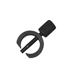
Good for safe hand removal
Removes clock hands using screw pressure to lift the hands evenly. D-type design fits many common hand stems and helps avoid damaging the dial when preparing mock-ups or swapping hands.
Practical tolerances to aim for:
Center hole ID: allow about +0.2–0.5 mm over the shaft diameter for smooth fit. Radial clearance (hand to dial): target 0.5–1.5 mm to prevent rubbing when humidity or play occurs. Hand‑to‑hand gap: keep 1–3 mm between minute and hour hands to avoid contact. Mounting hole positional tolerance: +/- 0.2–0.5 mm depending on part precision.These ranges suit hobby and most workshop replacements; tighter tolerances may be required for high‑precision restorations.
Quick fixes
High-impact measurement answers
Which surfaces must be measured and reported?
Report dial OD, center‑hole ID, dial thickness at the shaft, countersink/bezel depth, and mounting‑hole offsets. These define mechanical fit and hand clearance.
What if the model number is missing?
Provide top and side photos with a ruler and three numbers: OD, center hole ID, usable shaft length. Sellers often ID movements from photos and pivot spacing.
Do threads and flats count toward shaft length?
Measure total shaft length and usable exposed length from the dial face; mark where threads or flats start. Threads count only if used to hold the nut—specify thread diameter and pitch.
When to accept adapters versus exact replacements?
If differences are within ~0.5 mm for cosmetics or 0.1–0.2 mm for precision, adapters or light filing usually work. For complex stepped shafts prefer exact matches or custom adapters.
Order packet
Final ordering packet: measurements, photos, next steps
- Provide one labeled measurement block with all critical dimensions and tolerances.
- Attach five photos: full dial with scale, center-aperture with calipers, shaft/profile, pivot hole close-up, and movement/backside.
- Request seller confirmation of fit, compatible part numbers, usable tolerances, and return/exchange terms before purchase.
Copy‑and‑paste order text: list overall dial diameter; center hole ID (and axis if oval); shaft type, usable exposed length, diameters, thread size/pitch; pivot hole diameters and step depths; hand‑hole sizes and pocket depths; bezel clearance. Attach photos named to match each measurement. Then contact the seller with the packet and request explicit fit confirmation, any adapter recommendations, expected tolerances, and the return/exchange policy.